CAD to STL
To produce a model from your data, we require you send us your 3D CAD model as a STL file. The parameters you use to generate this file will directly influence the quality of the model. This page contains some general information on how to output STL from several CAD packages. Please consult your manuals for your software as these instructions may not correspond to the version you are using.
Definition
STL is the standard file type used by most or all Rapid Prototyping systems. A STL is a triangulated representation of a 3D CAD model. The code for one triangle is shown below:
solid test
facet normal 0 1 0
outer loop
vertex 0 4 0
vertex 0.517638 3.93185 0
vertex 0.5 3.93185 -0.133975
endloop
endfacet
endsolid test
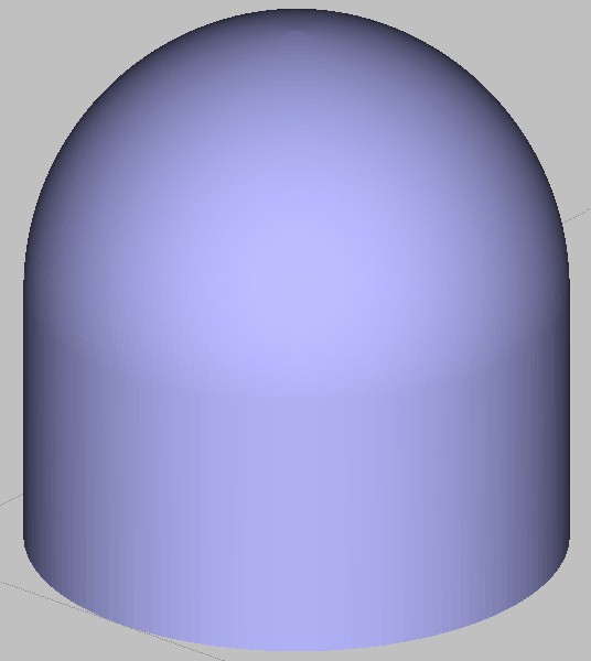
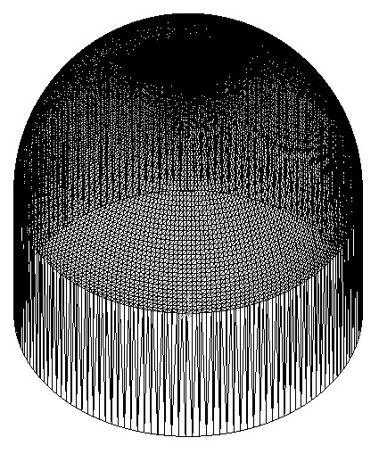
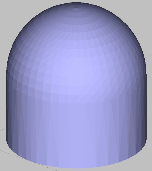
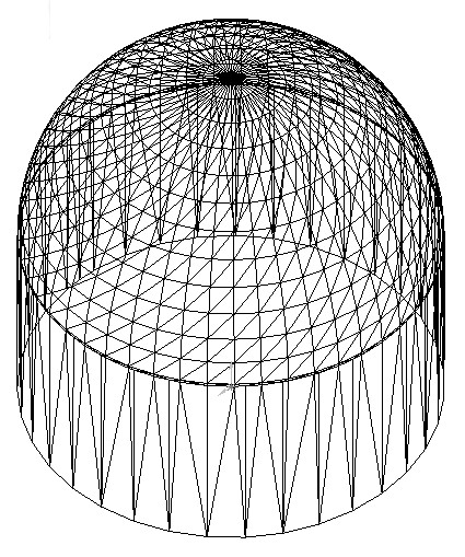
The triangulation of a surface will cause faceting of the 3D model. The parameters used for outputting a STL will affect how much faceting occurs. Below are some examples of a fine and coarse STL. (click on image to enlarge)
   
You cannot build the model any better or smoother than the STL. So if the STL is coarse and faceted, that's what you will see in the model.
In the CAD package, when exporting to STL, you may see parameters for chord height, deviation, angle tolerance, or something similar. These are the parameters that affect the faceting of the STL.
You don't necessarily want to go too small. The finer the STL the larger the file is in size, which will affect processing time in Insight as well as build time. Below is some information found on the Internet regarding exporting to STL from various CAD packages.
STL Creation
Software packages: Again, these are only general guidelines and may not work or produce the best possible STL files in some cases. Please consult your user's guide or the software developers for more information or technical support.
| Alibre | AutoCAD (Versions: R14-2000i) | I-DEAS | IronCAD | Mechanical Desktop | ProE |
| ProE Wildfire | Rhino | SolidDesigner (Version 8.x) | SolidEdge |
| SolidWorks | Think3 | Unigraphics | CADKey | Inventor |
Alibre
- File
- Export
- Save As > STL
- Enter File Name
- Save
AutoCAD (Versions: R14-2000i)
Your design must be a three-dimensional solid object to output an STL file.
- Make sure the model is in positive space
- At the command prompt type "FACETRES"
- Set FACETRES BETWEEN 1 &10. (1 Being low resolution and 10 high resolution for STL Triangles)
- Next, at the command prompt type "STLOUT"
- Select Objects
- Choose "Y" for Binary
- Choose Filename
I-DEAS
- File > Export > Rapid Prototype File > OK
- Select the Part to be Prototyped
- Select Prototype Device > SLA500.dat > OK
- Set absolute facet deviation to 0.000395
- Select Binary > OK
IronCAD
- Right Click on the part
- Part Properties > Rendering
- Set Facet Surface Smoothing to 150
- File > Export
- Choose .STL
Mechanical Desktop
- Use the AMSTLOUT command to export your STL file.
- The following command line options affect the quality of the STL and should be adjusted to produce an acceptable file.
- Angular Tolerance - This command limits the angle between the normals of adjacent triangles. The default setting is 15 degrees. Reducing the angle will increase the resolution of the STL file.
- Aspect Ratio - This setting controls the Height/Width ratio of the facets. A setting of 1 would mean the height of a facet is no greater than its width. The default setting is 0, ignored.
- Surface Tolerance - This setting controls the greatest distance between the edge of a facet and the actual geometry. A setting of 0.0000 causes this option to be ignored.
- Vertex Spacing - This option controls the length of the edge of a facet. The default setting is 0.0000, ignored.
ProE
- File > Export > Model (or File > Save a Copy)
- Set type to STL
- Set chord height to 0. The field will be replaced by minimum acceptable value.
- Set Angle Control to 1
- Choose File Name
- OK
ProE Wildfire
- File > Save a Copy > Model
- Change type to STL (*.stl)
- Set Chord Height to 0. The field will be replaced by minimum acceptable value.
- Set Angle Control to 1
- OK
Rhino
- File > Save As
- Select File Type > STL
- Enter a name for the STL file.
- Save
- Select Binary STL Files
SolidDesigner (Version 8.x)
- File > Save
- Select File Type > STL
- Select Data
- Click OK
SolidEdge
- File > Save As
- Set Save As Type to STL
- Options
- Set Conversion Tolerance to 0.001in or 0.0254mm
- Set Surface Plane Angle to 45.00
- Save
SolidWorks
- File > Save As
- Set Save As Type to STL
- Options > Resolution > Fine > OK
- Save
Think3
- File > Save As
- Set Save As Type to STL
- Save
Unigraphics
- File > Export > Rapid Prototyping
- Set Output type to Binary
- Set Triangle Tolerance to 0.0025
- Set Adjacency Tolerance to 0.12
- Set Auto Normal Gen to On
- Set Normal Display to Off
- Set Triangle Display to On
CADKey
- Choose Stereolithography from Export options
- Enter the Filename
- Click OK
Inventor
- Save Copy As
- Select STL
- Choose Options > Set to High
- Enter Filename
- Save
Information provided by Stratasys Corporation |